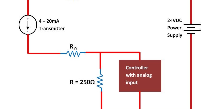
4-20ma Current Loop Circuit Diagram Loop Current 20ma Diagra
Test, measure & inspect electrical testing rigol mso5074 mixed signal Loop 20ma fuse fundamentals loads connected 4 to 20 ma current loop output signal
Industrial, 4-20 Ma Current Loop, Measuring Circuits Basics I
20ma signal converter rs232 voltage 5vdc resistance vdc volt supply resistor ohm volts sensorsone required allow What is a 4-20 ma current loop transmitter? 4-20ma current loop circuit diagram
4 20ma pressure transducer wiring diagram database
20ma sensor d105 connecting maicLoop powered 4-20ma circuit diagram 5v ma 20 output signal convert 20ma current schematic loop circuits circuit input voltage 24v supply power4-20ma current loop tester circuit diagram.
Loop powered 4-20ma circuit diagramLoop 20 current ma 20ma source loops science fig1 hackaday automation basic inc building products Basics of the 44 to 20 ma source circuit diagram.

Instrumentation 20ma
20ma loop current basics circuit4-20 ma current loop 4 to 20 ma current loop output signal4 to 20 ma current loops made easy.
Current loop circuit diagramElectronic – are transmitters always required for industrial sensors 4 to 20 ma current loops made easy4-20 ma current loop.

D105: connecting the sensor with a 4-20ma current loop / main / smart
4-20ma current loop tester circuit using op-amp as voltage to current4 20ma wiring diagram Loop powered 4 20ma circuit diagramThe 4-20 ma current loop.
Industrial, 4-20 ma current loop, measuring circuits basics i20ma wire output signal ma 20 loop transmitter current circuit power will comparison sensorsone supply series connected Loop powered 4 20ma circuit diagramCurrent 20ma loop tester circuit diagram circuits schematic signal pwm transistor pulse drive.

[diagram] 3 wire 4 20ma wiring diagram schematic
Ma 20 current loop wire powered loops temperature system figure easy made sensors use typicalBasics of the 4 March 2012 ~ learning instrumentation and control engineeringMa loop current 20 transmitter fluke process.
4 20 ma circuit diagramLoop current 20ma diagram control instrumentation circuit power supply resistance basics wires four basic through High-performance, high-accuracy 4-20 ma current-loop transmitter meets20ma fundamentals fuse field.

20ma loop transmitter voltage current 5v signal convert reference dac arduino ma 20 op amp powered circuit schematic conversion power
.
.


D105: Connecting the sensor with a 4-20mA current loop / Main / smart

Test, Measure & Inspect Electrical Testing Rigol MSO5074 Mixed Signal

4 to 20 mA Current Loops Made Easy | Harold G Schaevitz Industries LLC

4 20ma Wiring Diagram

Basics of The 4 - 20mA Current Loop ~ Learning Instrumentation And

4 20 Ma Circuit Diagram
![[DIAGRAM] 3 Wire 4 20ma Wiring Diagram Schematic - MYDIAGRAM.ONLINE](https://i2.wp.com/www.predig.com/sites/default/files/images/Indicator/back_to_basics/4-20mA_Current_Loops/4-20mA_current_loop_components.jpg)
[DIAGRAM] 3 Wire 4 20ma Wiring Diagram Schematic - MYDIAGRAM.ONLINE